 Tweet
Tweet
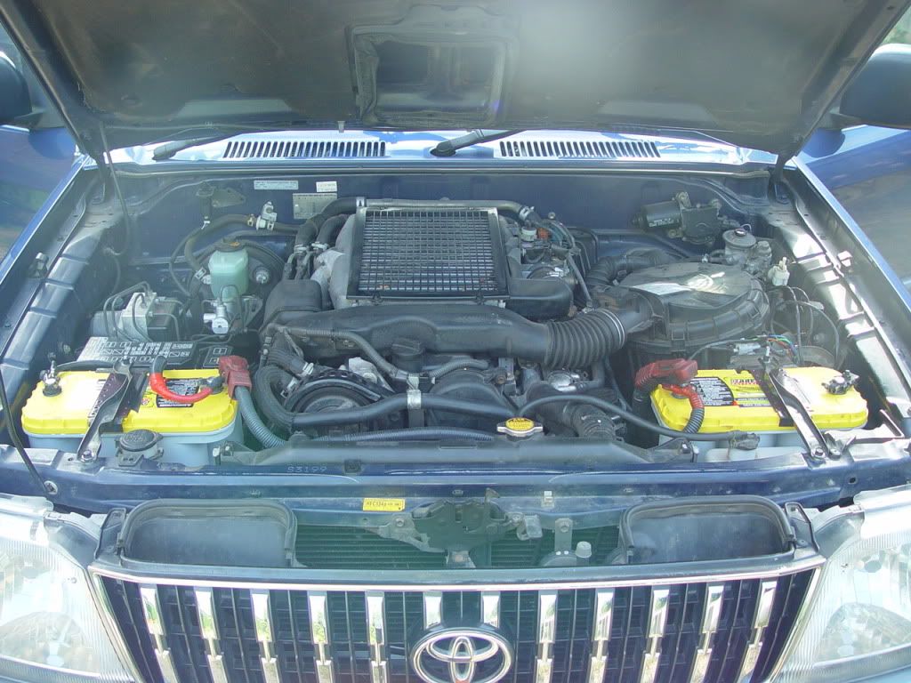
I'm trying to make sense out of the dual battery setup in my '01 series 90 D-4D, in preparation for a winch setup. They appear to be hooked up in parallel, but not exactly! There's a bit of wizardry going on with the negative terminals, that's not reflected in the schematics. Here is what I've noticed:
1. The positive terminals are connected to one another using a heavy duty cable. Fine.
2. The driver side negative terminal is connected to chassis ground using a fairly thin wire.
3. However, the passenger side negative terminal is NOT connected to chassis ground. There is a thick cable going down, which I suspect is connected to the starter motor.
4. When I measure the resistance between the two negative terminals, I get a reading of 3 or 4 ohms. Which is quite a lot! (For comparison, the reading between the positive terminals is 0.1 ohms, which is probably at the limit of the ohmmeter, so it may be even less.)
What this suggests is that the two batteries might be effectively isolated from one another, for any high-current applications. The resistance might be high enough that no more than a few amps would flow between the two negative terminals. But, where does this resistance come from? The schematics (TSB BE−0025) have been drawn as if there is only one battery! So, they don't give any clue as to what's going on.
Does anyone know how the batteries are really hooked up? Are there any schematics floating around that accurately reflect what's going on? Which battery would be better to hook the winch up to? Does the alternator have overload protection? (In the schematics, it's connected to a 150A fuse, but obviously I wouldn't want to blow that.)
My thinking, at this point, is that if the winch was hooked up to the passenger side battery, and the winch had a good ground to chassis connection, the negative cable would effectively short-circuit the above 3-4 ohm resistance. This would enable a much greater amount of current to flow through the thin negative-to-chassis cable on the driver side battery, and might overload it under heavy winching. So, it might be safer to hook the winch to the driver side battery. Does that make sense?
I was thinking of installing an isolator switch, but given the above resistance, this might not be necessary.
BlueRock
Comment